I believe that many people may not be aware of the math that goes into building guitar amplifiers and guitar effect pedals on a daily basis. I had the opportunity to visit a local company’s workshop and talk to the builders about some of the mathematics they use. I learned that mathematics is incorporated into this industry in many ways. It is not just used in the financial side of things; it is also used in the designing/building side of things. While some of this mathematics is more basic and is taught at the secondary level, other mathematic is more complex and is taught in mathematics/engineering courses at the college level. I am going to discuss three examples of how mathematics is used in the building and design of guitar pedals. The first two examples deal with mathematics that is introduced at the middle school. The third example involves a topic covered at the high school level.
Resistors In Series and In Parallel: Utilizes the use of reciprocals and basic arithmetic.
Depending on the circuit (in audio-based circuits), you may need to use a certain resistance that isn’t manufactured or in stock from an electronic components supplier.
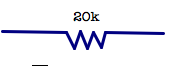
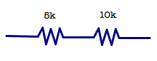
For example, say you need a 20k resistor (20,000 ohms [Ω]) of resistance, but you don’t have a 20k resistor in stock. You can run resistors in series.
is the same as,
When run in series, just add the values 10k + 10k =10,000 + 10,000 = 20,000 = 20k
So, you can run two 10k resistors in a series to obtain 20k Ω of resistance.
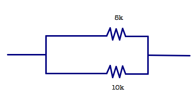
In parallel, its slightly more complicated. Say you have,
What is the amount of resistance?
These are not in series. If they were, it would be 15k Ω of resistance, shown as
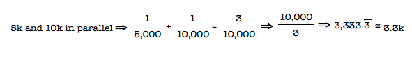
To find the resistance of the resistors run in parallel, find the reciprocals of all the values, find their sum, and then find the reciprocal of the sum. Observe,
So, a 5k and 10k resistor run in parallel provides approximately 3.3k Ω of resistance.
Placement of Potentiometers: Utilizes the x-y plane, the distance formula, and basic arithmetic.
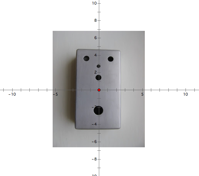
The pedal enclosure is the box that the circuit board and the other components of the pedal go in. A schematic sheet usually accompanies the pedal. On this schematic sheet, an x-y plane is laid over the pedal.
The center of the enclosure is located at the origin.
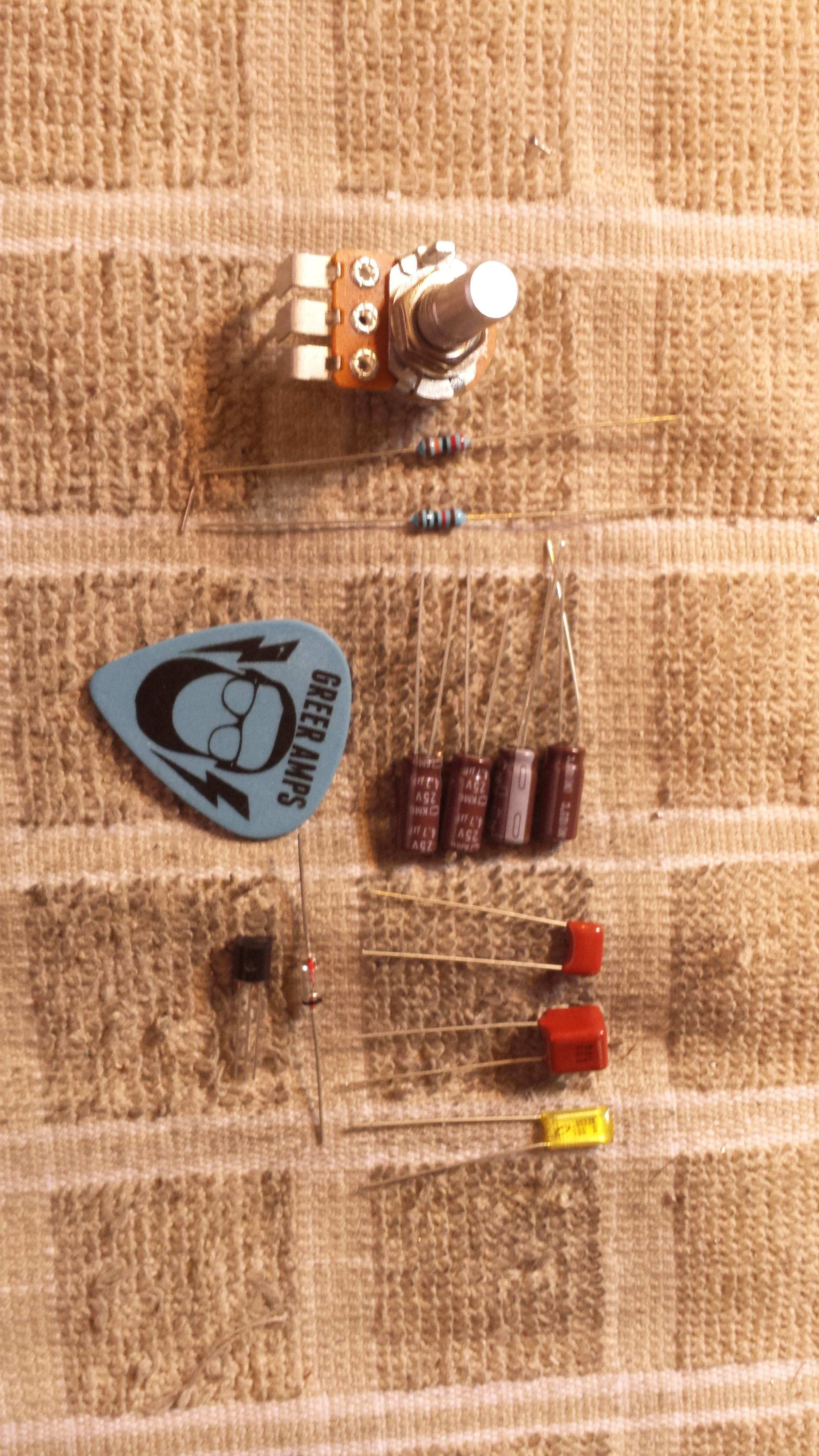
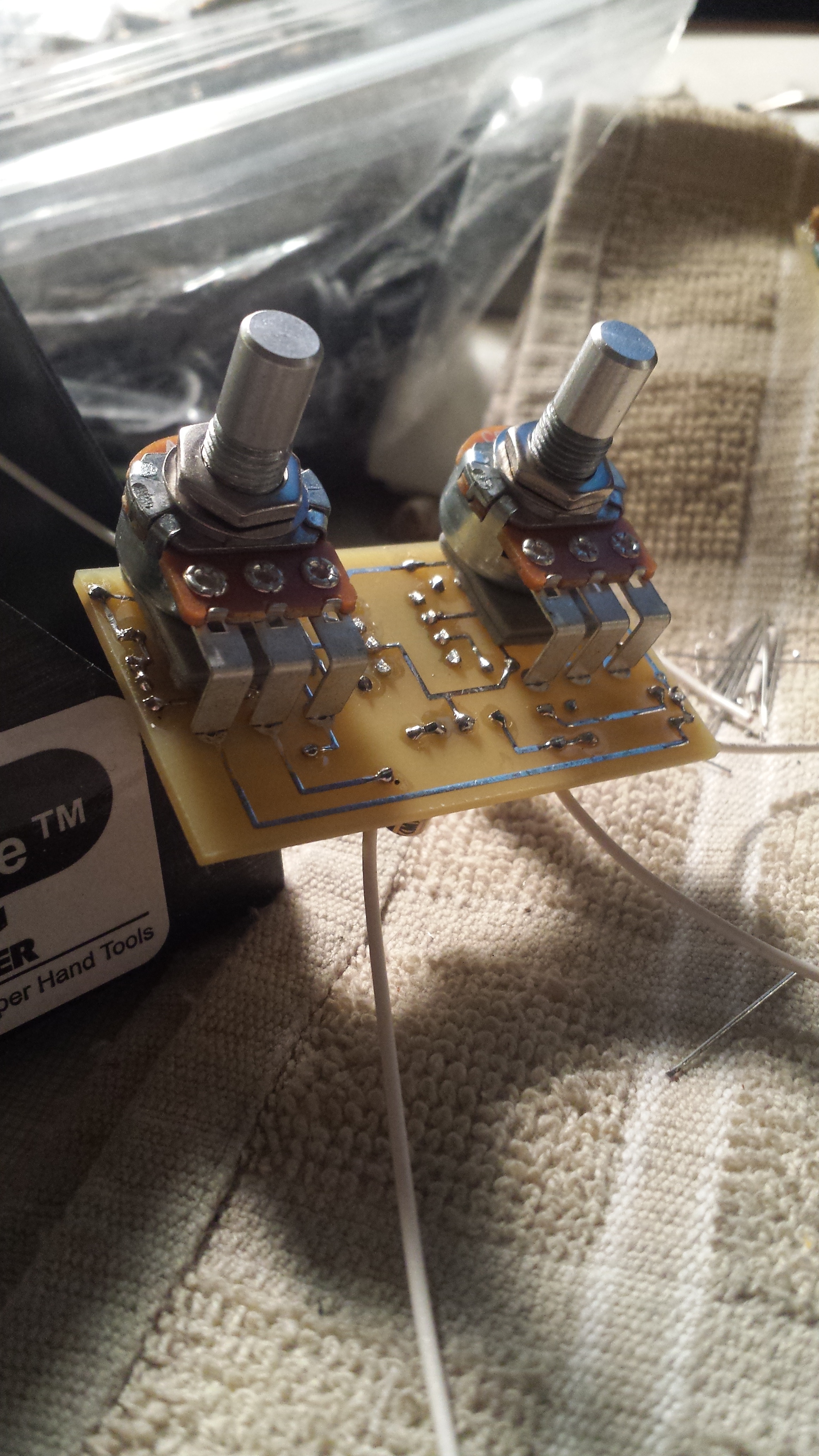
Knobs will go where the holes are. Knobs are called “pots” short for potentiometer, which is a type of resistor. The pots (the part of the knob, that’s inside the pedal) are mounted onto the circuit board. The shaft of the pot is the part of the knob you see and turn on the outside of the pedal. Turning the knobs will change the resistance. Below, is a picture of the pots mounted on the circuit board.
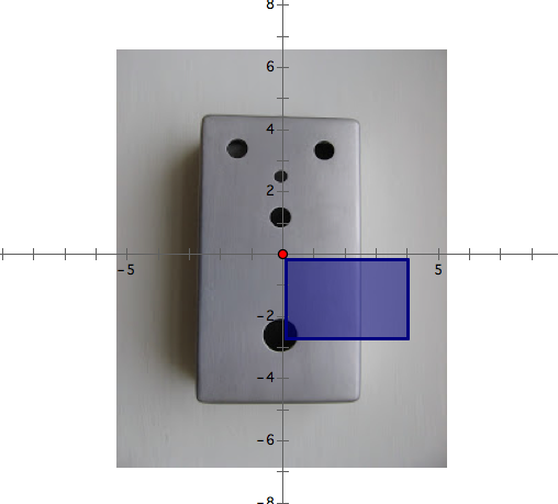
The centers of the holes on the pedal enclosure are given as coordinates. When designing the circuit board, you have to plan where to put the pots on the circuit board so that once they are secured to the board, they can just slide into the holes on the enclosure. The program used by the builders does not allow them to just type in the coordinates of the holes as they appear on the schematic sheet. The program places the circuit board in the 4th quadrant with the top left-hand corner of the circuit board near the origin.
The blue rectangle is the circuit boad
This is not where the circuit board is actually located inside the pedal. To use the program to design the circuit board, the builders must use mathematics to translate the circuit from its current position down to the 4th quadrant. One way to do this is by using the distance formula and basic arithmetic.
I asked the builders if there was a program out there that would determine the placement of the pots without having to translate the circuit board.
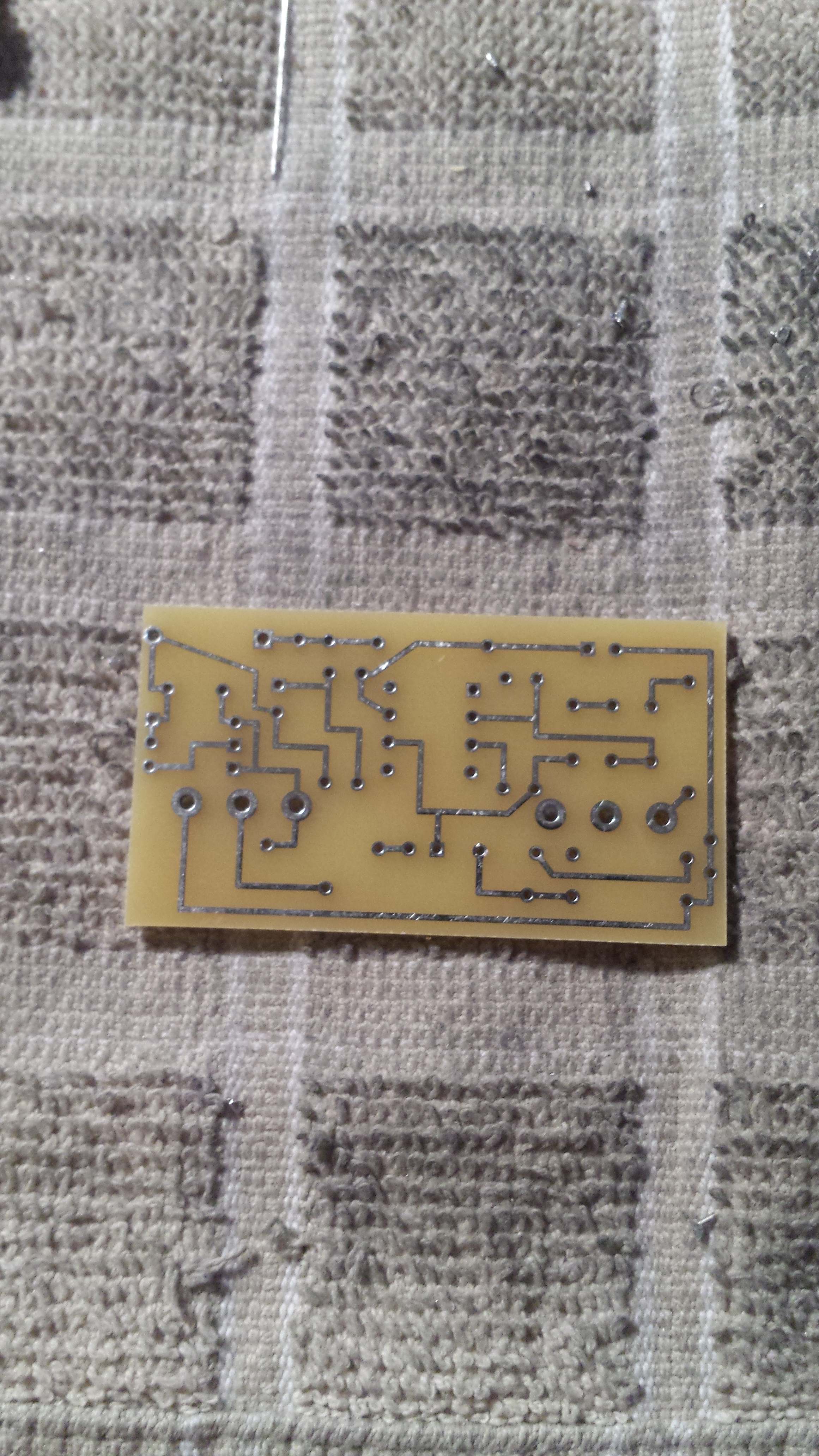
They said that the program they are using is cheaper than others and that the time spent doing the calculations by hand is worth the money they save. They alsosaid that the program also puts the design into a format that allows another company to manufacture the circuit boards. Below, is a picture of a circuit boad.
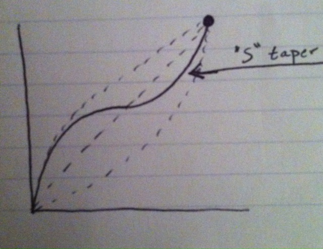
Common Types of Potentiometer Tapers In Audio Electronics: Utilizes linear and logarithmic graphs
The tapers determine how the turning of the knobs affect the electrical flow, hence, the sound (or Volume) is usually an audio taper.
Linear (B)
Reverse Audio (C)
So, a 100k pot comes in various types: A100k, B100k, & C100k. This is how they are written on the pots.
An uncommon taper is the “S” taper, written on the pot as w100k.